Isolation in dc-dc converters has many different uses besides just protection against electric shock. A recent blog posting by Recom Power explains the various grades of isolation and how they are implemented in typical low-power dc-dc converters.
Although dc-dc converters are available without input-output isolation, many use an internal transformer to electrically (galvanically) separate the output from the input. This makes dc-dc converters very versatile. Having outputs that are floating with respect to the input means ground loops can be broken to reduce noise in electrical systems, the output polarity can be freely chosen, and, of course, the isolation barrier can form an important safety element to prevent electric shock and to reduce other hazards caused by fault conditions.
Since the output is isolated from the input, the choice of the ‘zero' reference voltage for the input or output side is also arbitrary. For example, an isolated dc-dc with 5V output can be used to change voltage level and polarity (e.g. +5V out from -48V in), add to an existing voltage (e.g. generate +20V from a +15V supply) or create a dual output from a single supply (e.g. ±5V from +5V). Figure 1 shows some possibilities.
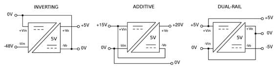 Figure 1: Some different ways of using an isolated dc-dc converter
The isolation grade is dependent on the robustness of the isolation barrier. For dc-dc converters, the most commonly used classes are:
- Functional - the output is isolated, but there is no protection against electric shock
- Basic - the isolation offers shock protection as long as the barrier is intact
- Supplementary - an additional barrier to basic, required by agencies for redundancy
- Reinforced - a single barrier equivalent to two layers of Basic insulation
So how do these classes translate into practical transformer construction?
Functional Isolation
For functional isolation, transformer primary and secondary windings are typically wound directly over one another, relying on the thickness of the wire lacquer for insulation (Figure 2). This method has the advantage of being low cost and yielding a very compact-sized transformer which, despite the small size, can withstand up to 4kVdc isolation voltage testing, but with limited duration and as a non-repetitive test.
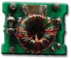 Figure 2: Ring core transformer with functional isolation
Typical applications for functional isolation converters include non-safety-critical systems, where the isolation is primarily used to break ground loops, block conducted interference paths or to provide a change in functional ground reference voltage. In these applications, an isolation fault would not cause injury or serious damage to the equipment, or often even stop the application from working. The isolation provides added security against interference or increases reliability, but is not safety-related.
A good example is a CAN-bus data communication system. The CAN-bus specification does not specify that the bus wiring must be isolated, but in practice, isolating the interface eliminates many potential sources of error or interference with the data transmission. As both ends of the bus are isolated, the transmitter and receiver can sit at different ground potentials without problem. Any electrical interference is ignored by the differential bus topology, without the danger of external fields inducing an overall current flow in the wiring. This is one of the reasons why isolated CAN-bus systems are often used in heavy industrial automation plants and production processes. Figure 3 shows an evaluation board that uses one of Recom's SMD dc-dc converters to provide isolated bus power.
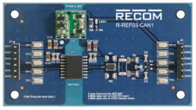 Figure 3: Isolated CAN-bus evaluation board
Basic Isolation
Basic isolation grade requires secure insulation between the primary or secondary windings, rated at the system voltage - lacquer insulation on winding wire is insufficient as pin-holes can be present. In a basic-insulation grade transformer, the input and output windings are not wound directly over one another, but are separated by a minimum distance or with a physical barrier, such as an agency-approved insulating film (Figure 4).
This method can be used in larger sized transformers where there is enough room to add layers of tape between the windings.
 Figure 4: Bobbin transformer with basic isolation
For compact dc-dc converters, ways must be found to provide basic isolation without making the transformer too big. Figure 5 shows a transformer which uses a separation bridge to physically separate the windings. In addition, the ferrite ring core is plastic coated, so it is also independently isolated from the windings. Recom's RxxPxx and RxxP2xx series use this type of construction which is production-tested up to 6.4kVdc, in a compact SIP8 package (19.5 x 12.5 x 9.8mm).
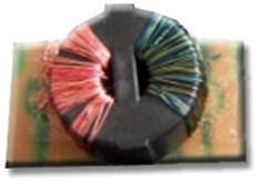 Figure 5: Bridge-design transformer
There is also another way of making a basic-insulated transformer, using a potted core. In this method of construction, the ferrite core with one winding (usually the primary) is placed in a plastic pot which is then filled with epoxy. A lid is fitted and then the second winding is wound around the whole construction through the hole in the middle (Figure 6). The insulation is not dependent on the lacquer around the transformer wires, but is independently ensured via the plastic pot and epoxy filling. Production processes ensure that the quality and thickness of epoxy and lid meet the minimum agency requirements for basic insulation at the stated system voltage.
 Figure 6: Potted core transformer construction
Recom's RP-xxxx series uses this type of construction to offer 5.2kVdc isolation test voltage rating in a compact SIP7 package (19.6 x 10.2 x 7mm). Although more complex to manufacture, this ‘potted-core' method gives a very compact transformer with a reliable and consistent insulation performance which does not deteriorate with time. This makes the RP series one of the most reliable high-isolation dc-dc converters in Recom's portfolio, used in many different demanding applications from military aircraft to high-voltage test equipment.
Reinforced Isolation
With reinforced isolation, input and output windings are separated by a larger distance or at least two physical barriers, each equivalent to basic insulation rating (Figure 7).
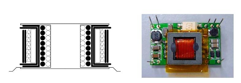 Figure 7: Example of a reinforced transformer construction with a basic and supplementary layer of insulation (shown as the thick black lines in the diagram)
The multiple layers of insulation make the transformer bulkier however, which limits the amount of miniaturization possible. One way around this problem is to use triple insulated (TIW) transformer wires which are already classified as offering reinforced insulation. Using this type of wire, Recom has succeeded in creating the REM1 series of dc-dc converters which are medically certified to the IEC/EN/UL 60601-1 safety standard with 4 kVac / 1 minute isolation, 2 x MOPP (Measures of Patient Protection) and 250Vac working voltage isolation in only a SIP 7 package.