Radiocrafts offers an updated software development kit (SDK) for RIIM™ (Radiocrafts' IP Mesh), an embedded RF system designed to be an all-inclusive, easy to use mesh, with direct IP addressing. The RF protocol is the IEEE802.15.4 g/e standard.
RIIM includes an Intelligent C-programmable I/O (ICI), which makes it possible to directly interface to any sensor or actuator, and, it supports Mist Computing. RIIM™ does not require any license or subscription fee.
RIIM targets networks where fast time to market and low engineering effort is desired. Additionally, it targets networks with the following requirements:
- Industrial grade reliability
- Adaptation to customer needs
- Long range and great coverage
- Low Power
- Simple network setup
Examples of specific types of applications that RIIM is intended for include but are not limited to:
- Smart city
- Energy management systems
- Light control
- Climate control
- Access control and security
- Agriculture
The updated SDK has various new additions including:
- Windows support in addition to Linux
- A new node configuration - Leaf Node
- A new example ICI application for sleepy nodes
- Automated scripts to generate a flash image and upload it to the module
- The SDK itself also has an html file where Radiocrafts has laid out detailed descriptions of all necessary instructions needed to use the SDK effectively.
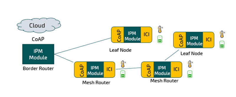
The RIIM SDK supports a new node configuration, the Leaf Node, which the RC1882CEF-IPM module can be configured as. The RIIM node configurations now consists of:
- Border Router - As a ROOT node, it acts as the base of the mesh network. It can connect to an external network via ethernet or custom user application on other interfaces such as UART.
- Mesh Router - As a Mesh Router node, it will be able to route packets up and down in the RIIM mesh network.
- Leaf Node - As a Leaf node, it can only route packet to its parent. This configuration is used for very low power network nodes.
The RIIM SDK has a new example ICI application for sleepy nodes. This example is meant to show the low power capabilities of a RIIM node. The example shows how you can set a node to switch-off its radio and go to "sleep" mode. It can also be programmed to wake-up periodically to send a message then return to sleep mode.
In addition to sleepy nodes, the RIIM SDK includes six ICI applications including:
Cloud example - This example demonstrates how to connect the RIIM development kit to the cloud.
- A child node reads its temperature and sends it directly to the cloud
- The Border Router uses DHCP to connect to a local LAN, it sends status of the network to the cloud
- The example uses Thingsboard.io as example cloud solution
Large Network example - This example is made to see the formation, topology and status of a large (or small) network
- Child nodes connect to the Border Router and periodically sends CoAP packages where the payload is a counter
- The Border Router periodically prints out the whole network topology and also the received CoAP messages it gets from the child nodes
Local sensors example - This example demonstrates how to interface sensors via various interfaces
- A child node (running on a Radiocrafts SB) reads one of the following sensors and sends the data as a JSON object (as a CoAP payload) to the Border Router: ADC, Sensirion SHT35 Temperature/Humidity-sensor, ST LIS3DE Accelerometer
- The Border Router prints out the received CoAP message TA example
- This example demonstrates the OTA functionality of RIIM
- The Border Router uses CoAP towards the /ota resource on a child node to send a new user application
- The receiving node does nothing except periodically writing out a string indicating which application is running
- After OTA transmission is complete, the receiving node is reset, and the new user application is running
Sensor board example - This example interfaces all functions on the Radiocrafts SB
- The application reads data from all sensors present on the SB
- Sensirion SHT35
- TI HDC2010
- Sensirion SGPC3
- ST LIS3DE
- Analog Light Sensor
- ADC
- Honeywell SL353LT
- User push button
- It also controls the LEDs
- Periodically, all the measured values are output to the UART and one measurement is transmitted to the Border Router
- The Border Router prints out the received CoAP messages
UART example - This example demonstrates the use of the UART
- UART setup
- UART transmission with callback function
- UART reception with callback function and timeout