SiC FETs in 2.2kW / 80+ Titanium Bridgeless Totem-Pole PFC Reference Design
In Cree's CRD-02AD09N reference design board, the main power board carrying PFC circuit has been implemented on a 4-layer printed circuit board (PCB). Cree's C3M0065090J, 900V, 65mohm, TO-263-7 silicon carbide (SiC) MOSFET has been used in this reference design. Illustrated above is a block diagram of the CRD-02AD09N.
Cree's C3M0065090J SiC MOSFET consists of a fast intrinsic diode with low Qrr and a very low output capacitance (60pF). Cree's C3M0065090J SiC MOSFET also comes in a compact surface mount package with extended leads for higher voltage capability with low source inductance (<2nH).
A traditional analog PFC controller from Infineon Technologies AG (P/N: ICE3PCS01G) has been selected for Cree's CRD-02AD09N reference design board. ICE3PCS01G is a 14-pin wide input range controller for active PFC converters.
Cost-Effective Approach to Current Sensing
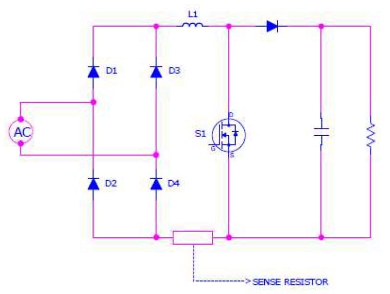
For the average current mode control method, inductor average current is required for the current loop. For conventional PFC circuits, inductor current sensing can be achieved by using a shunt resistor at the return path of inductor current, as shown in the figure below:
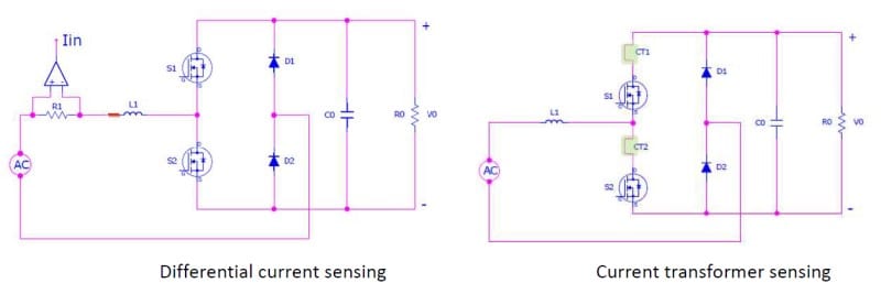
Another method of current sensing is to use a differential mode amplifier. However, the PF may be hurt because of the current sensing noise (since the current sensing voltage should be low to minimize the power loss), and the cost of parts for this method are higher than the costs for a shunt resistor current sensing solution.
Alternatively, the inductor current can be reconstructed by using a MOSFET current. Due to the different conduction path of the inductor current, a total of two current transformers (CT1 & CT2) are required for the current sensing. The figure below shows the position of the required current transformers. The input current can be reconstructed as the sum of the three sensed currents. Cost, effect of magnetizing current and size are limiting factors for this approach. The use of a differential-mode amplifier versus two current transformers is illustrated below:
A better cost-effective approach is followed in Cree's CRD-02AD09N reference design board. During the positive half cycle, the voltage drop across the current sense resistor CS1 will give the current sense signal and during the negative half cycle, the voltage drop across the current sense resistor CS2 will give the current sense signal.
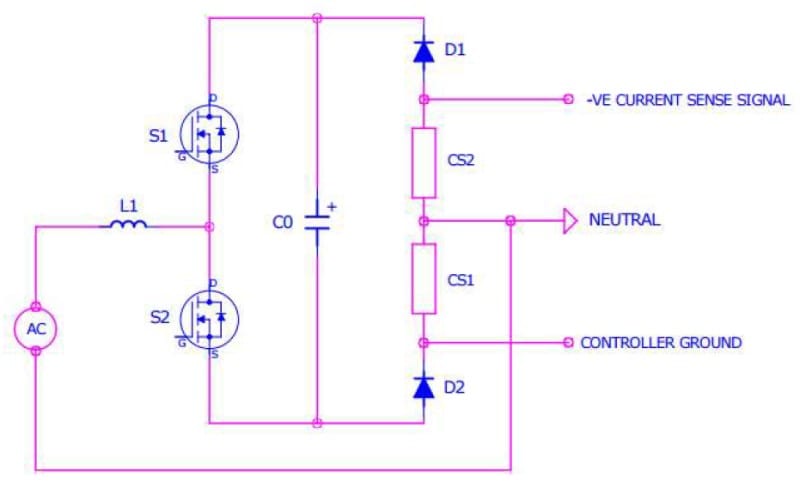
In this approach, illustrated above, (and unlike the current transformer (CT) approach), there is no need to rectify current sense signal. 8mΩ current sense resistors (CS1 and CS2) have been selected for this application.
Summary of CRD-02AD09N Reference Design Features
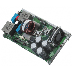 CRD-02AD09N reference design board
- Highly efficient and low cost solution of bridgeless totem-pole PFC topology based on Cree's (C3M™) 900V SiC MOSFET in a TO-263-7 Package
- Comfortably achieve Titanium standard by having 98.5% efficiency while THD < 5% under all load conditions
- Innovative resistor based current sensing solution
- Distortion less inductor current at zero crossing during all load conditions
- Reduced Bill of Material (BOM) by the use of general purpose diodes in place of low frequency switches
- Documentation includes bill of materials (BOM), schematic, board layout, application note and power point presentation


