New Power Capacitor Tech for Wide Band-Gap Semiconductors
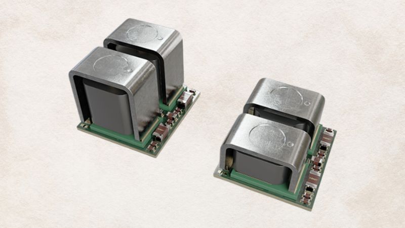
The new B25640* series of HF power capacitors from TDK Corp. is especially tailor-made for silicon-carbide (SiC) semiconductors. With rated voltages of between 700- and 2200-Vdc and capacitance values from 370- to 2300-µF, the capacitors are suitable for the new generation of converters for traction, industrial drives and renewable energy applications.
With the aid of CAD and FEA (finite element analysis) simulation software TDK has now developed HF (high-frequency) power capacitors with an optimized internal design. Even at the high frequencies and temperatures at which wide band-gap semiconductors are operated, these capacitors offer high performance with low losses, thanks to a minimized ESR (see graph above).
 The new HF power capacitors.
With the COC-PP dielectric the capacitors can also be operated without voltage derating at temperatures of up to 125°C. One great advantage of the new capacitors is their extremely low ESL value of just 10nH. This means that, even at high, rapidly switched currents, their voltage overshoot remains very low, so that in most cases they even make snubber capacitors unnecessary.
You may also like: AEC-Q200 1100V Metallized Polypropylene Film Capacitors
Conventional semiconductors based on silicon are being replaced by wide band-gap technologies based on GaN and SiC. These demand a great deal from the passive components - particularly the dc link capacitors. Leveraging its experience in materials and design, TDK is able to offer innovative solutions, enabling the advantages of the new semiconductors.
For switched applications in power electronics such as power supplies and converters, wide band-gap semiconductors offer the advantage that they can be operated with switching frequencies in the hundreds of kHz range. At the same time, they feature steep pulse edges, thereby achieving greater energy efficiency.
Due to these high switching frequencies, film capacitors are increasingly being used as dc link capacitors. In order to minimize the lead lengths, and thus the parasitic inductances, the capacitors are connected directly to the wide band-gap modules by means of busbars.
The problem here is that wide band-gap semiconductors are operated with high barrier termination temperatures, which can also be conducted via the busbars to the dc link capacitors. The temperature limit of conventional film capacitors with a dielectric of biaxially oriented polypropylene (BOPP), however, is only 105°C.
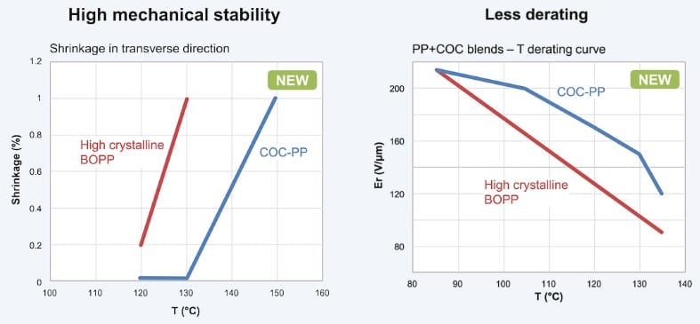 Left: At temperatures of up to 130 °C the new COC-PP material exhibits no shrinkage in a transverse direction. Right: Voltage derating of the new material is also significantly better.
New dielectric allows high-temperature applications
TDK has succeeded in developing a dielectric that can also be used continuously at high temperatures. This involves a combination of two basic materials. One component is semicrystalline polypropylene, which is ideal for processing into films; the other is amorphous cyclic olefin copolymer (COC), which can tolerate high temperatures.
The resulting dielectric (COC-PP) can be used at temperatures in excess of 125 °C with considerably lower derating, while retaining the good self-healing properties of BOPP. In addition, this enables extremely thin films of just 3µm to be manufactured. Figure 1 shows the significantly improved shrinking and derating behavior of COC-PP in comparison with conventional BOPP.
Outstanding performance
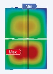 A frequency of 5kHz produces a significant inhomogeneous distribution of current, and therefore losses, over both windings.
Like all capacitors, film capacitors also feature a complex ESR, a series connection comprising an ohmic and a capacitive part. Accordingly, this produces a frequency-dependent resistance that increases sharply as the frequencies rise. This rise is essentially caused by inhomogeneous impedances, skin effects and winding geometries, leading to unwanted resonances and electromagnetic effects. The result is a heating of the capacitor.
This has a particularly negative effect if the internal design of a capacitor consists of several windings. Different internal lead lengths and other factors then lead to a pronounced frequency-dependent current distribution across the individual windings, as shown in the illustration at the left.