Dual-Axis Drive with 3-Phase Gallium-Nitride Inverter Stages – Reference Design
The just-released TIDM-02007 reference design from Texas Instruments presents a dual-axis motor drive with three-phase gallium-nitride inverter stages using Fast Current Loop (FCL) and Software Frequency Response Analyzer (SFRA) technologies on a single C2000™ controller.
The FCL takes CPU and CLA parallel processing technique to achieve a substantial improvement in control bandwidth and phase margin, to reduce the latency between feedback sampling and pwm update, to achieve higher control bandwidth and maximum modulation index, to improve dc bus utilization by the drive and increase speed range of the motor.
Integrated the SFRA tool enables developers to quickly measure the frequency response of the application to tune speed and current controllers. Given the system-level integration and performance of C2000 series MCUs have the ability to support dual-axis motor drive requirements simultaneously that delivers very robust position control with higher performance. The software is released within C2000WARE MotorControl SDK.
Recommended for you: Low-Cost Gallium Nitride Crystal Manufacturing for Power Devices
Features
- Three-phase GaN inverter with wide-input voltage from 12-V to 60-V and 7-Arms, 10-A peak output current per phase
- Precision-phase current sensing with high accuracy (0.1%) based inline shunt resistor on BoosterPack™
- Implement dual-axis motor drive with Fast Current Loop (FCL) on a single F2837x or F28004x MCU using the existing hardware kits
- Working software is compatible with F2837x or F28004x as a starting point for those with expertise or limited expertise
- Enables outer position and velocity loop, and inner torque loop using FCL technique simultaneously to achieve fast response on each motor
- Integrated SFRA tool to support tuning speed and current loops online separately
- Incremental system builds are designed to verify the major software modules used in the system
- Low pwm update latency (1.02µs on F2837x, 2.02µs on F28004x) to achieve higher control bandwidth and modulation index
System Description
 Key system specifications for the TIDM-02007 reference design (click on table to enlarge)
High-performance motor drives in servo drive and robotics applications are expected to provide high precision and high control bandwidth of current, speed, and position loops for superior control of end applications such as robotics, CNC machines, and so forth. Since the current loop makes up the inner most control loop, it must have a high bandwidth to enable the outer speed or position loops to be faster. Hence, a high bandwidth Fast Current Loop (FCL) is needed in high performance industrial servo control applications. However, the delays due to ADC conversion and algorithm execution limit the current controller bandwidth to about a tenth of the sampling frequency.
This reference design shows the implementation of fast current loop on a F2837x/F28004x C2000 controller running two motors simultaneously, and verifies the frequency response of the control loops using TI's SFRA tool. The control bandwidth of fast current loop and the operating speed range of motor are experimentally verified.
The design guide documents the test platform setup, procedure and the quantitative results obtained. It is important to note that when the pwm carrier frequency is 10kHz, the current loop bandwidth obtained is 5kHz for a phase margin of 45° over a wide speed range compared to the traditional MCU based systems, FCL software can potentially triple a drive system's torque response and double its maximum speed without increasing the pwm carrier frequency.
You may also like: Gallium Nitride Chargers Are Here: Navitas at CES 2020
The F2837x and F28004x series of C2000 MCU enable a new value point for dual-axis drives that also delivers very robust motion-control performance. The value comes not only from the achievable control performance and ability to drive two motors concurrently, but also from the high degree of on-chip integration of other key electronic system functions. Since both F2837x and F28004x devices support CPU and CLA cores, CPU offload encoder feedback and torque control processing to the CLA to maximize the performance of dual-axis servo drive.
Block Diagram
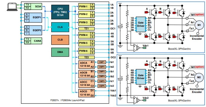 TIDM-02007 reference design block diagram (click on image to enlarge)
The block diagram above illustrates the dual-axis motor drive based a single C2000 MCU system of the TIDM-02007 reference design, which includes the following elements:
- One controller board, a TMS320F28379D LaunchPad™ or TMS320F280049C LaunchPad
- Higher clock frequency CPU, Trigonometric Math Unit (TMU) and control law accelerator (CLA) that parallel process floating point calculation of FOC and FCL algorithm to get high speed, precision performance.
- Four high-speed precision 12-bit and 16-bit ADCs on F2837x, or three high speed precision 12-bit ADCs on F28004x for sensing the motor phase current and DC bus voltage.
- Two independent Enhanced Quadrature Encoder Pulse (QEP)-based encoder connectors for sensing the exact rotor position for dual-axis motor drive.
- On-board USB can work as both a debugger for debugging and programming interface and a virtual COM port to a PC with a serial monitor running for SFRA software.
- Two Inverter boards, BOOSTXL-3PHGANINV
- Wide Input Voltage Range 12-V to 60-V with 7-ARMS Output Current per Phase.
- Precision in-line phase current sensing with 5-mΩ shunt for motor drive that can be connected to the ADC of F28379D or F280049C.
- Three LMG5200 GaN half-bridge power stages with embedded driver that are compatible interface With 3.3-V I/O for F28379D or F280049C LaunchPad.