Amiri McCain, an applications engineer with ON Semiconductor, recently completed a three-part blog series that discusses how to make accurate shunt resistor connections for optimum performance with current sense amplifiers (CSAs), such as the NCS21xR series and the NCS199AxR series from ON Semiconductor.
The first blog of this series discusses how to diagnose shunt resistor connection errors. According to Mr. McCain, this is, by far, the most common issue engineers have when using current sense amplifiers. The first blog is written to help users figure out how to debug these measurement errors quickly and accurately. The schematic of the NCS213R test circuit (illustrated above) is discussed in the final installment of this three-part series.
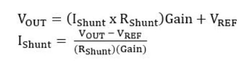
An important factor to keep in mind is that the current sense amplifier is actually detecting a voltage potential across its differential inputs and is accurately amplifying a voltage, not a current; thus the current is measured indirectly. Using the measured output voltage, the amplifier gain, the reference voltage and the value of the shunt resistor, the current flowing through the shunt resistor can be calculated:
The bulleted list below, along with the Decision Tree Figure and Debug Table below can be used in diagnosing shunt current measurement errors for any current sense amplifier circuit.
- Current sense amplifiers are voltage amplifiers.
- Measure the voltage directly at the amplifier input pins. The results may be different than when measured across the resistor.
- The amplifier output should be the measured voltage directly across the inputs (VShunt) multiplied by the amplifier gain.
- Most often problems prove to be related to shunts and or shunt connections.
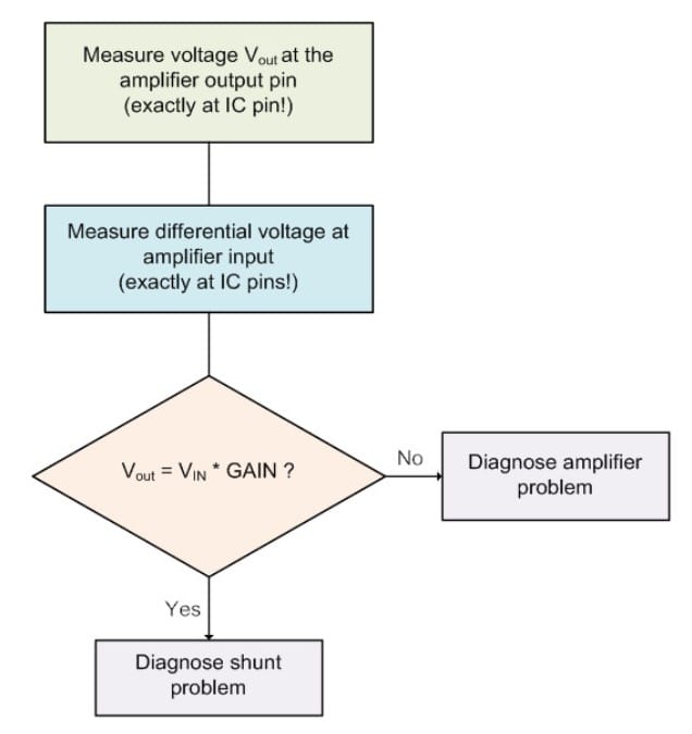 Shunt Current Measurement Error Diagnosis Decision Tree
Using the below Shunt Current Measurement Debug Table, it may be realized that the voltage measured directly across the amplifier input pins compared to the voltage measured directly across the shunt resistor is different by enough of an amount to cause errors that are unacceptable. In other words, the amplifier is accurately amplifying the wrong voltage! The final error at the output could easily be on the order of 10% to 15% or more due to poor PCB layout and connection to the shunt. The NCS21xR is going to accurately amplify the voltage that it sees directly at its input pins.
When your current sense amplifier is not providing the expected output voltage, use the straightforward approach to debugging your shunt connections described in this blog - this will reduce debugging time and help you to find the problem in minutes, not hours.
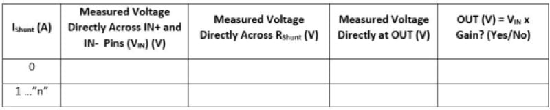 Shunt Current Measurement Debug Table Example
The second blog continues the discussion with the topic "Making Accurate Shunt Resistor Connections" and the third and final blog in the series focuses on "Good vs Bad Shunt Resistor Connections."