6.6kW Bi-Directional EV OBC with Silicon Carbide and Digital Control – Reference Design
The CRD-06600FF065N electric vehicle on-board charger (OBC) reference design from Cree uses the company's recently-introduced C3M0060065D, 60mΩ, 650V, silicon carbide MOSFETs (TO-247) in both the ac-dc and dc-dc stages. Two parallel MOSFETs are used in the high frequency half-bridge of the Totem-Pole PFC converter. A single MOSFET is used for the low frequency portion of the half bridge. The dc-dc stage uses a single MOSFET in both the primary (dc link) and secondary (battery) sides.
The design accepts a universal input, single-phase voltage between 90Vac and 265Vac and its output provides an isolated voltage between 250Vdc and 450Vdc. Both the input and output of the unit are protected by fuses. The input's under-voltage and over-voltage protection and the output's over-voltage protection are controlled by the digital controller. External power supplies for the Auxiliary Power Board and the heatsinks' cooling fans must be supplied separately.
The charger must be started with less than 1000W of load. The load may be increased incrementally after the output voltage has reached steady-state regulation. A graphical user interface (GUI) communicates to the unit via a CAN communication bus. It is used to display operational information and to provide related user controls.
Recommended for you: Silicon Carbide FETs Replace IGBTs in Karma Automotive Traction Inverters
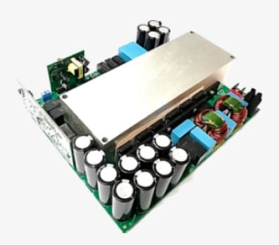 CRD-06600FF065N reference design
Features and Specifications
- Universal ac input voltage range.
- Isolated 250Vdc to 450Vdc output in ac-dc mode.
- Maximum output current is limited to 18A in ac-dc mode whenever the output voltage is between 250Vdc and 366Vdc and the input voltage exceeds 215Vac.
- Maximum output power is limited to 6.6kW in ac-dc mode whenever the output voltage is between 366Vdc and 430Vdc. It is linearly derated from 6.6kW to 5kW when the output voltage is between 430Vdc and 450Vdc and the input voltage exceeds 215Vac.
- Output power derates linearly from 6.6kW with an input of 215Vac to 2kW with an input of 90Vac while operating in ac-dc mode.
- Power is limited to 3.3kW in dc-ac mode.
- Output voltage is targeted at 220Vac/50Hz in dc-ac mode.
- Peak efficiency >96.5%.
- Auto-selection between ac-dc mode and dc-ac mode on every start-up.
- Synchronous rectification (SR) is automatically controlled with load. SR is typically enabled when the load current exceeds 5A. When it is below 2A, SR is disabled.
- Easy to test using a GUI communicating via CAN.
Circuit Operation
The front-end PFC stage uses a CCM Totem-Pole bi-directional topology and operates at 67kHz. It creates a dc link voltage that is followed by a bi-directional Isolated dc-dc CLLC resonant converter that operates in the 148- to 300-kHz range. The dc link voltage varies between 385Vdc and 425Vdc in order to optimize the OBC's efficiency as the charging battery voltage varies between 250Vdc and 450Vdc. This allows the peak efficiency of the OBC to reach 96.5% in both charging and discharging modes.
Both the input and output sides of the bi-directional isolated dc-dc stage use a full bridge switch arrangement isolated by a high frequency transformer. A unique tooled heatsink was designed to dissipate the heat generated by all of the power MOSFETs and power magnetics. This integrated heatsink approach allows the design to reach a power density of 54W/in3.
Digital Control
The control board which carries out the control algorithm of the entire system is designed around a Texas Instruments Inc. DSP (TMS320F28377D). The power for the control board is an isolated, 7V / 1A, power supply whose output is then tightly regulated to +5.0V by a linear regulator. This 5.0V voltage rail then supplies another precision linear regulator IC which provides both a 3.3V and a 1.2V voltage rail. All output pwm signals are buffered and shifted to a +5V level by level-shifter and buffer ICs before they are fed to their respective gate drivers.