6.6 kW SiC-based Bi-Directional EV On-Board Charger Reference Design
Wolfspeed has introduced the CRD-06600FF10N, 6.6kW bi-directional EV on-board charger based on Wolfspeed's C3MTM 1000V, 65mΩ SiC MOSFET which comes in a TO-247-4 package with a Kelvin source availability. The main features of Wolfspeed's C3M SiC MOSFETs include low switching losses, fast intrinsic body diode and high frequency operation which reduce the overall weight and size of the system and are intended to maintain high efficiency of the whole system.
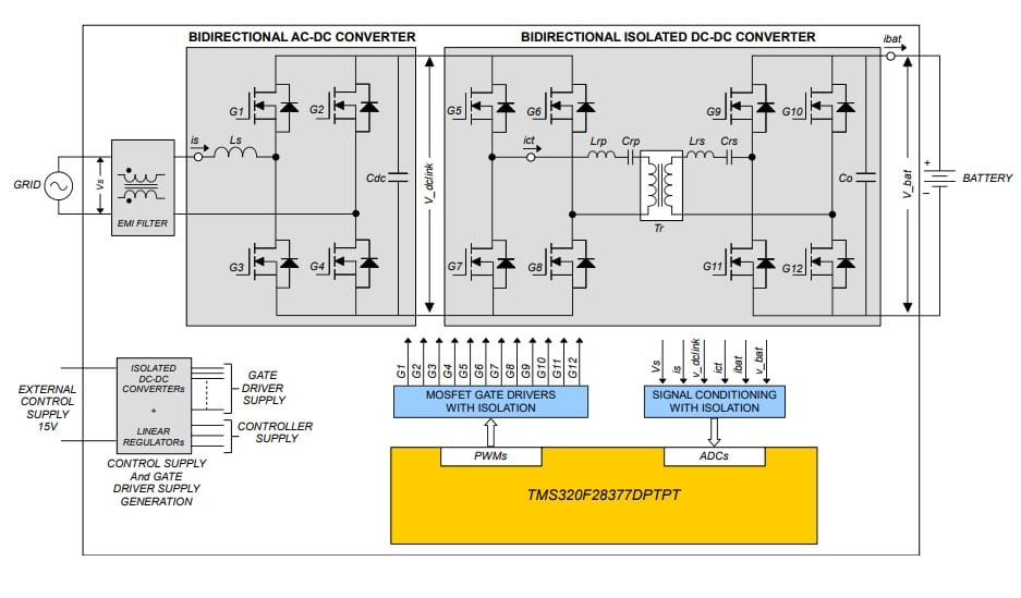
Wolfspeed's CRD-06600FF10N, 6.6kW bi-directional EV on-board charger comprises of two power stages: 1) bi-directional PFC stage and; 2) isolated bi-directional dc-dc stage.
The bi-directional PFC stage is based on the Totem-Pole PFC topology while the isolated bi-directional dc-dc stage is based on a CLLC topology with a variable dc link voltage. At full load, the dc link voltage varies according to the variations in battery voltage and the CLLC topology operates at resonance or close to the resonance frequency, which is intended to optimize the efficiency of the bi-directional CLLC converter and maintain overall efficiency that is better than a fixed dc link LLC converter.
 System Level Block Diagram of Wolfspeed's CRD-06600FF10N, 6.6 kW Bi-Directional EV On-board Charger (click on diagram to enlarge)
The system designed in the lab does not have a battery charging algorithm built in and designers may code their own battery charging algorithm in the DSP.
The ac-dc converter stage is configured as a totem pole PFC circuit in charging mode. The circuit has two half bridge circuits; one switching at high frequency of 67kHz and the other at the frequency of grid voltage, typically 50Hz. Both legs of the PFC circuit consist of two of Wolfspeed's 1000V, 65mΩ SiC MOSFETs in a parallel arrangement. The dc-dc bi-directional CLLC converter is comprised of 2 identical H-bridges separated by isolation transformer.
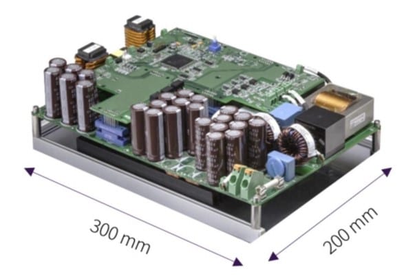 Physical Dimensions of Wolfspeed's CRD-06600FF10N, 6.6 kW Bi-Directional EV On-board Charger
A resonance frequency of 200kHz was selected for operation. All switches have isolated gate drivers with a separate isolated power supply. Ceramic de-coupling capacitors in proximity with small film capacitors have been used for the decoupling of the stray inductances.
Larger film capacitors have been used a little farther away from the devices for high frequency ripple current. A bank of electrolytic capacitors has been connected in series with dc link due to the availability of 680Vdc link voltage.
The controller card is a Texas Instruments DSP controller. Controller card is galvanically isolated from the power stage through isolated gate drivers, analog isolation amplifiers and the opto-isolators. For controller supply and driver supply, external isolated power supplies of 7V and 15V are connected to the control card.


